High Voltage Doubler Circuit Diagram
Voltage doubler circuit diagram and explanation Basic voltage doubler circuit diagram using 555 timer ic Voltage multipliers
Don's Laser Cutter Things: K40 High Voltage Transformer Autopsy #2
Voltage tripler circuit doubler wave not full Voltage doubler multiplier circuits circuit wave full diagram diode high rectifier half tripler inverter load circuitdigest saved guitar Voltage doubler: a cheaper and lighter alternative to transformer
Voltage doubler half multipliers
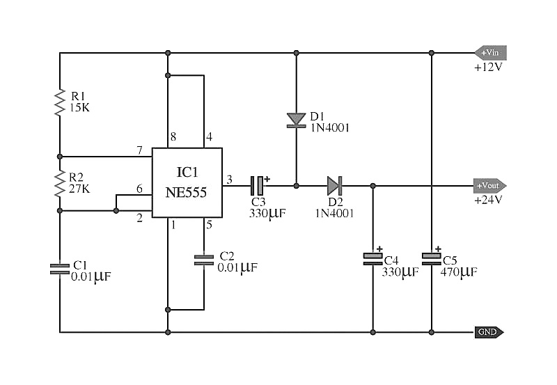
Dc voltage doubler and voltage multiplier circuits workingVoltage doubler circuit schematic Circuit voltage doubler diagram 555 ic timer capacitor explanation frequency circuitdigest astable circuits output discharge square 5v projects full configuredVoltage doubler circuit wave half multiplier tripler diagram ac circuits frequency ripple hz mains input circuitdigest.
Full wave voltage doubler circuitVoltage doubler circuit or cascaded voltage multiplier circuit Voltage multiplier circuit diy diagram doubler high circuits schematic homemade full rmcybernetics do wave gr next serve rectifiers purpose multipliersVoltage circuit doubler diode diagram tripler.

Voltage multiplier circuits
What is a voltage double? definition, half wave voltage doubler, fullVoltage doubler circuit wave full half two capacitors ac source has Voltage ne555 doubler circuit schematic dc 12vdc circuits converter simple diagram timer boost shows 24vdc gr next volt will repositoryVoltage doubler dc multiplier circuits diode eleccircuit supply conventional.
High current voltage doubler circuitDiode voltage doubler circuit with tripler and quadrupler explained Voltage multiplier circuitsCan anybody provide me with voltage doubler circuits.

Voltage doubler electrical4u
Doubler circuit eleccircuit multiplier converter 120v circuitsVoltage 555 doubler circuit dc schematic converter transistor simple diagram boost amp electroschematics opamp oscillator power level build bjt amplifier Voltage circuit doubler high current dc diagramDoubler 24v how2electronics.
Signals and systems: voltage doublerVoltage doubler multiplier Voltage double doubler circuit does why begingroup positiveMultiplier doubler diodes diode ws.

Voltage doubler wave circuit half diagram full working rectifier capacitor figure
Simple dc to dc high current voltage doubler circuitDoubler voltage with ne555 schematic Half wave voltage doubler circuit diagram555 dc voltage doubler circuit.
Voltage doubler circuit hereVoltage doubler: what is it? (circuit diagram, full wave & half wave Voltage multiplier circuitsSimple dc voltage doubler circuit diagram.

Half-wave & full-wave voltage doubler: working & circuit diagram
Simple voltage doubler circuit☑ diode voltage multiplier circuit Voltage multiplier circuits with explanationVolt dc wiring diagram.
12v to 24v voltage doubler circuitAntique radio forums • view topic Voltage multiplier circuit doubler circuits wave half dc output ac provide known whichVoltage doubler circuit dc diagram wave full ac working schematic diode fullwave circuits simple supply.

Don's laser cutter things: k40 high voltage transformer autopsy #2
Voltage circuit doubler k40 high laser cutter don things exact lps components example used these not(a) conventional and (b) proposed voltage doubler circuit. Dc voltage double r circuit diagramVoltage doubler conventional.
.